~F.R.E.D.A.~
Elizabeth Sonder

INTRODUCTION

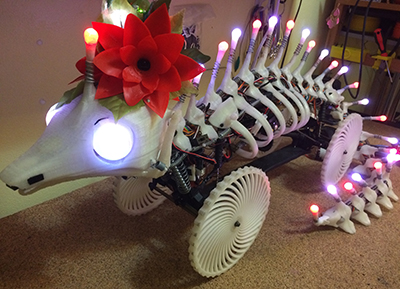
Fatuous Robotic Experiment in Draconiform Ambulation

Finished Robot Images

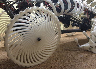
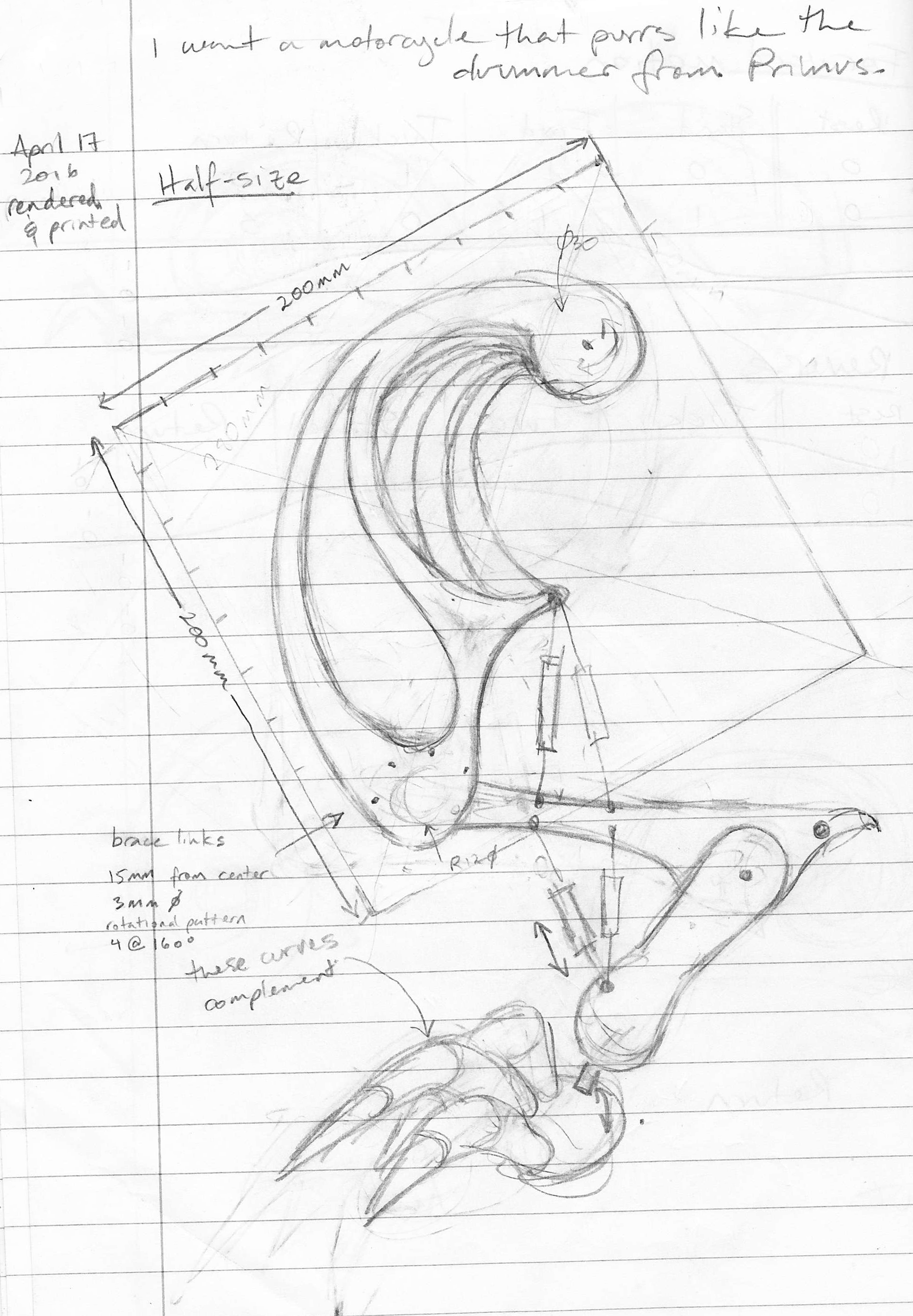
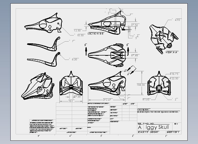
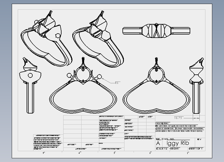
FREDA was chosen as a long-term project that would require skills far beyond my current capabilities, in order to help direct my focus in learning robotics. I wanted to start from the ground up, so I could understand each element along the way. I also wanted to make something weird, just for the fun of it.


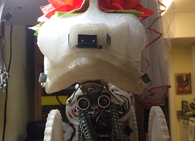
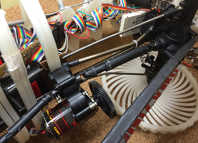
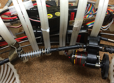
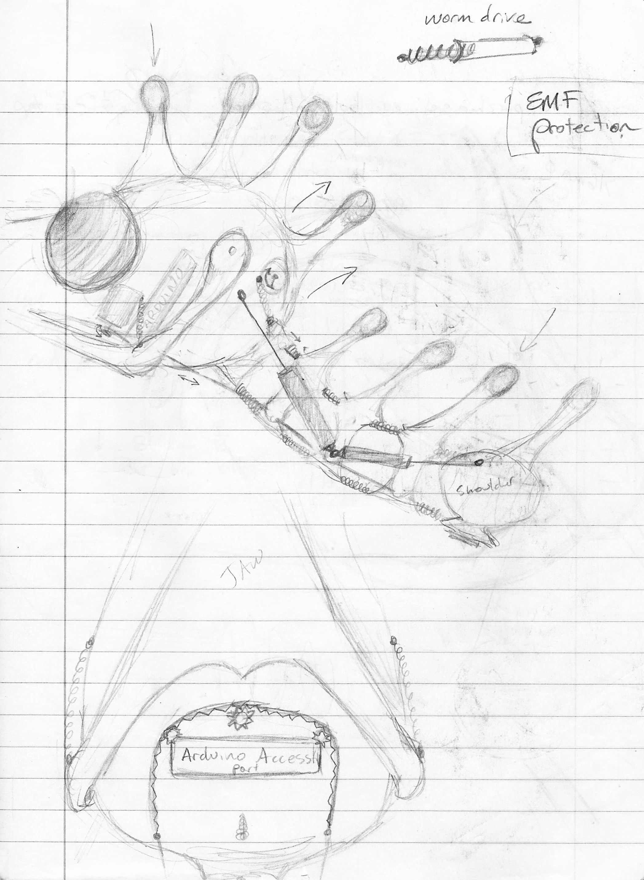
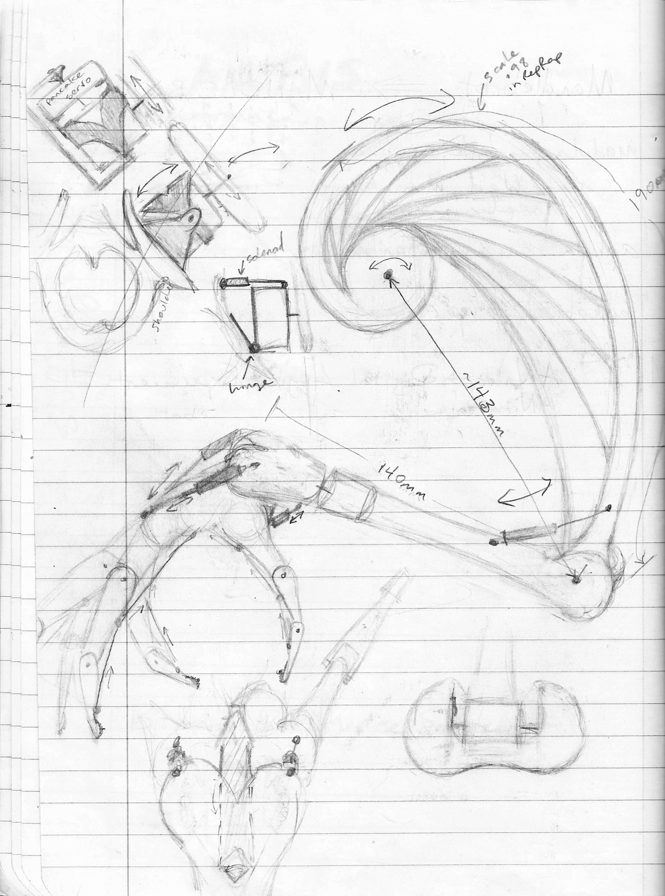
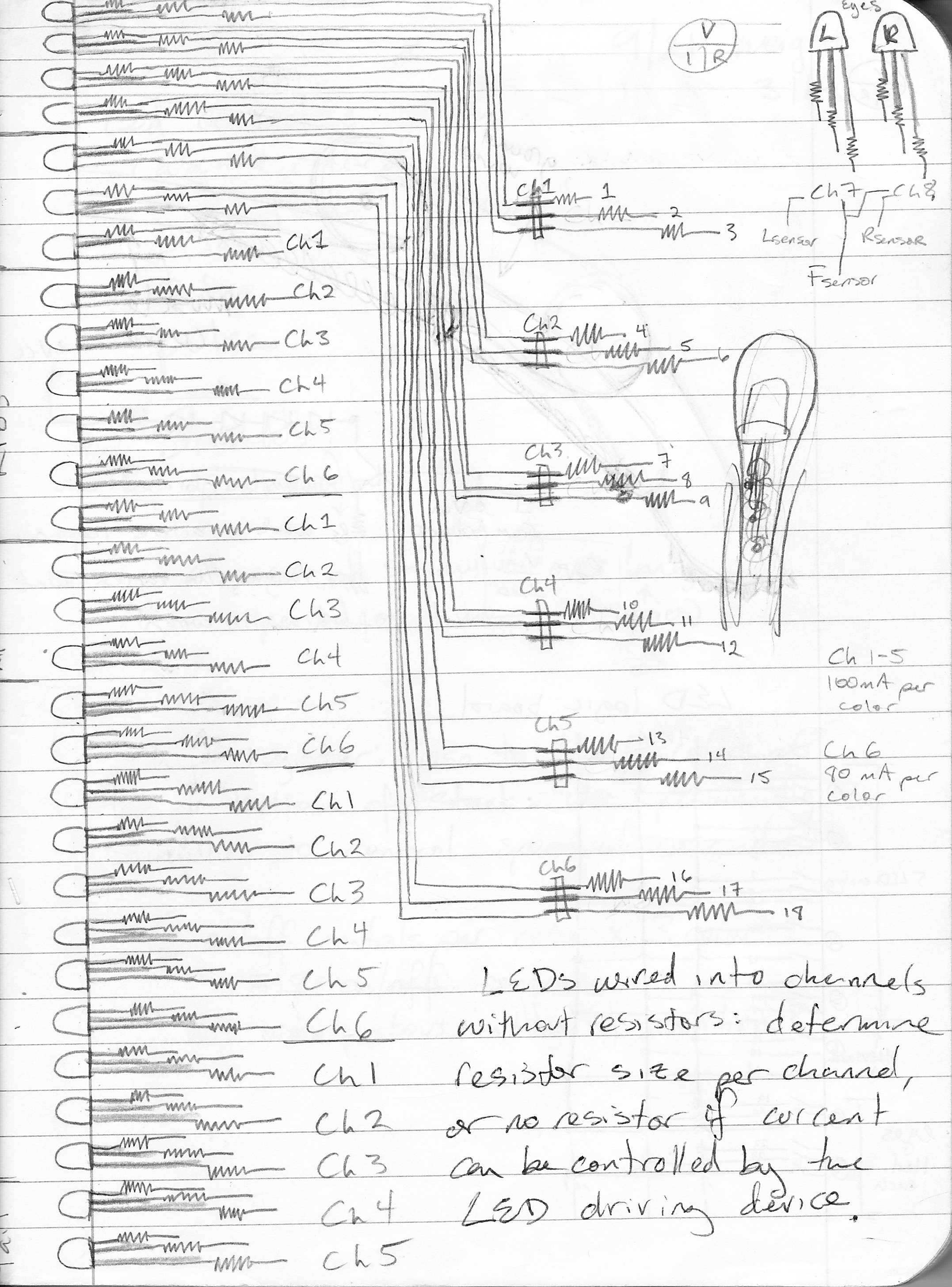
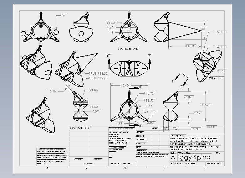
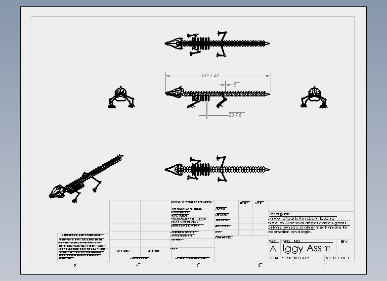
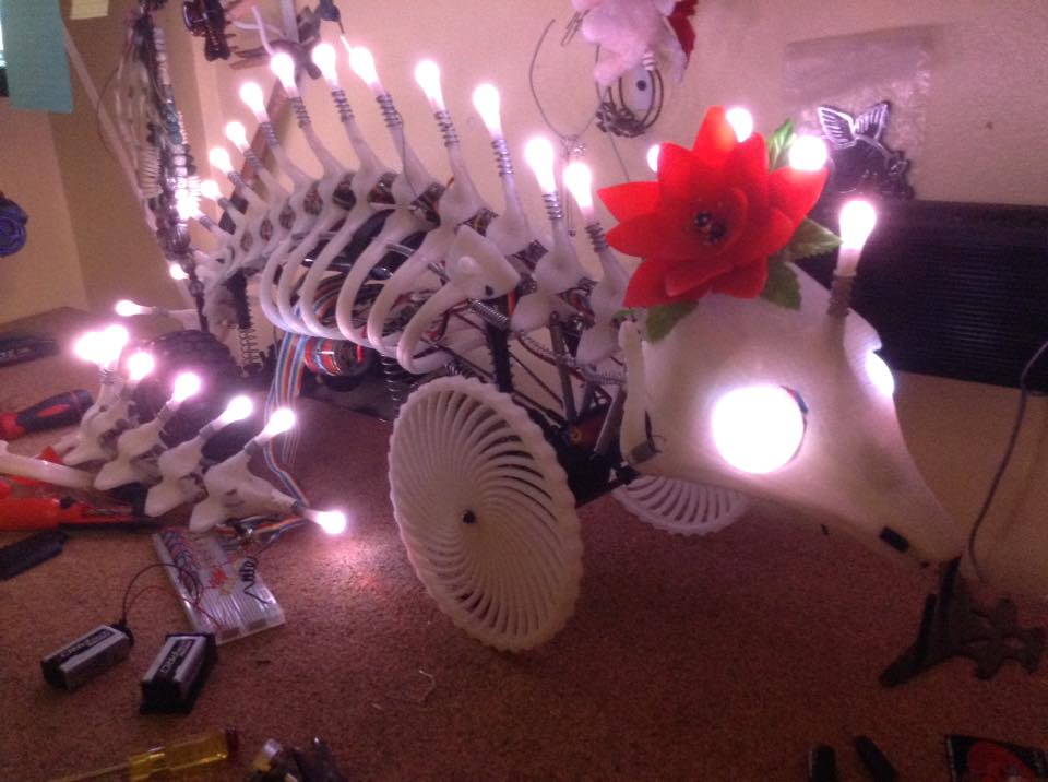
To get started on this project, I first had to learn Solidworks, in order to begin designing the chassis itself. I designed most of the chassis while taking a class at City College of San Francisco. I also took some basic electronics courses, and built a Velleman K8200 home 3D printer from a kit, which allowed me to practice electronics assembly with instruction before I attempted any from scratch. After printing the chassis, I wired up the 31 RGB LEDs housed along the spine and in each eye, as that was the accumulation of my ability at the time. After that, I enrolled in a beginning coding class and an Intro to Robotics course at UC Berkeley. What you are seeing on this site is the accumulation of everything up until the completion of these two courses.

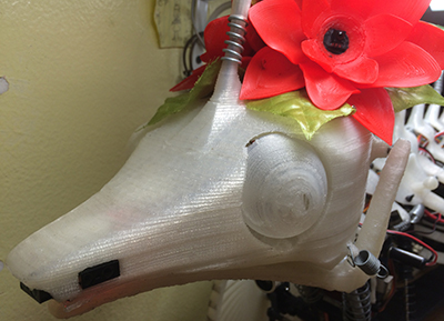
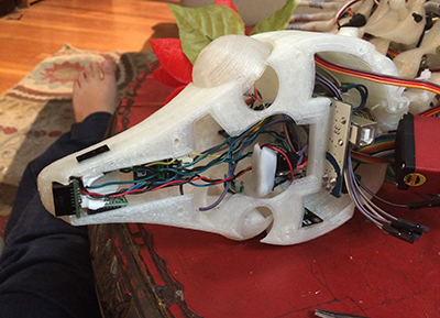
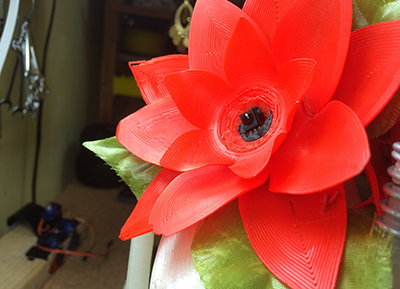
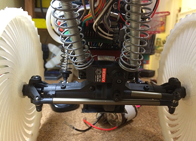
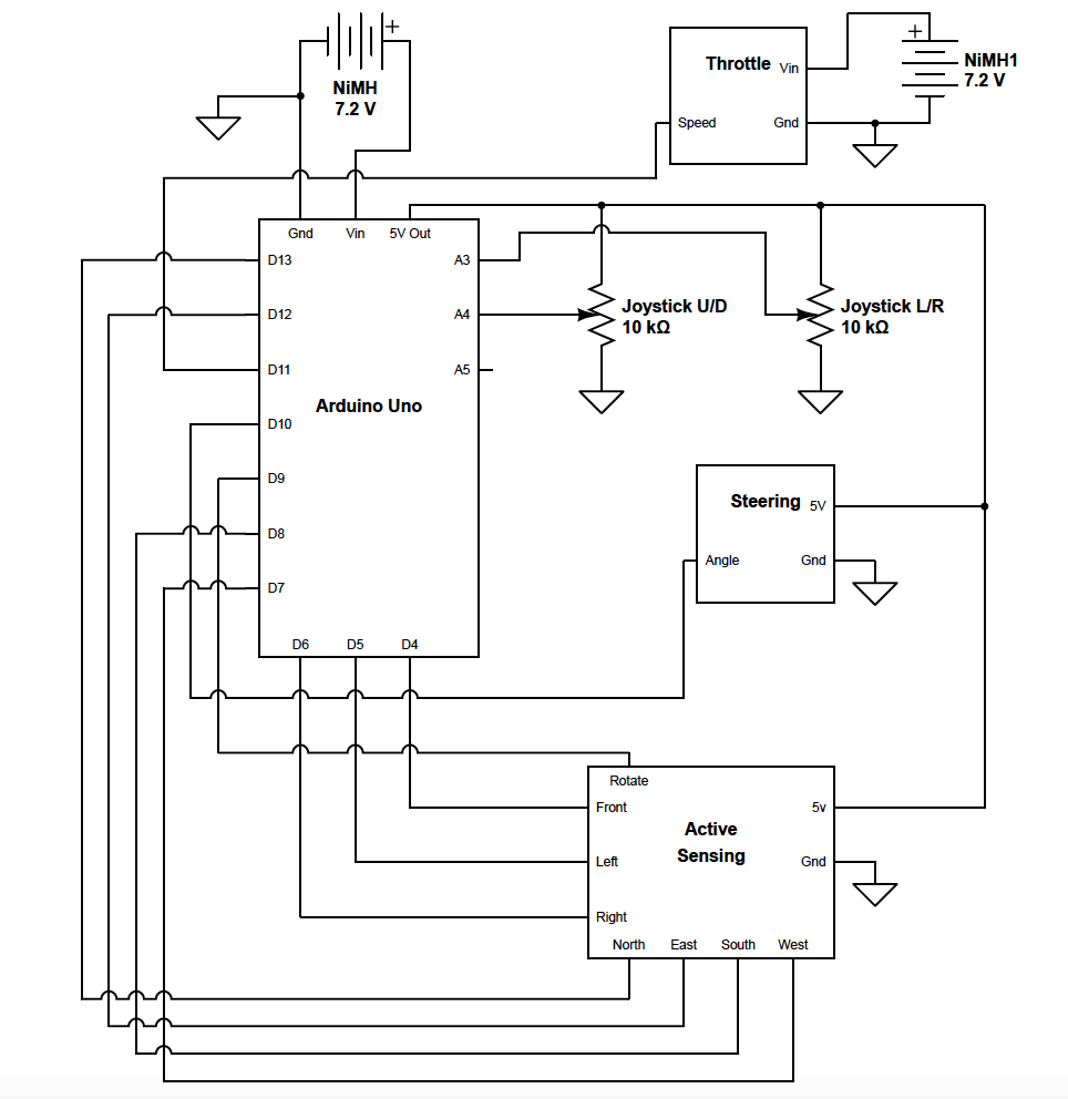
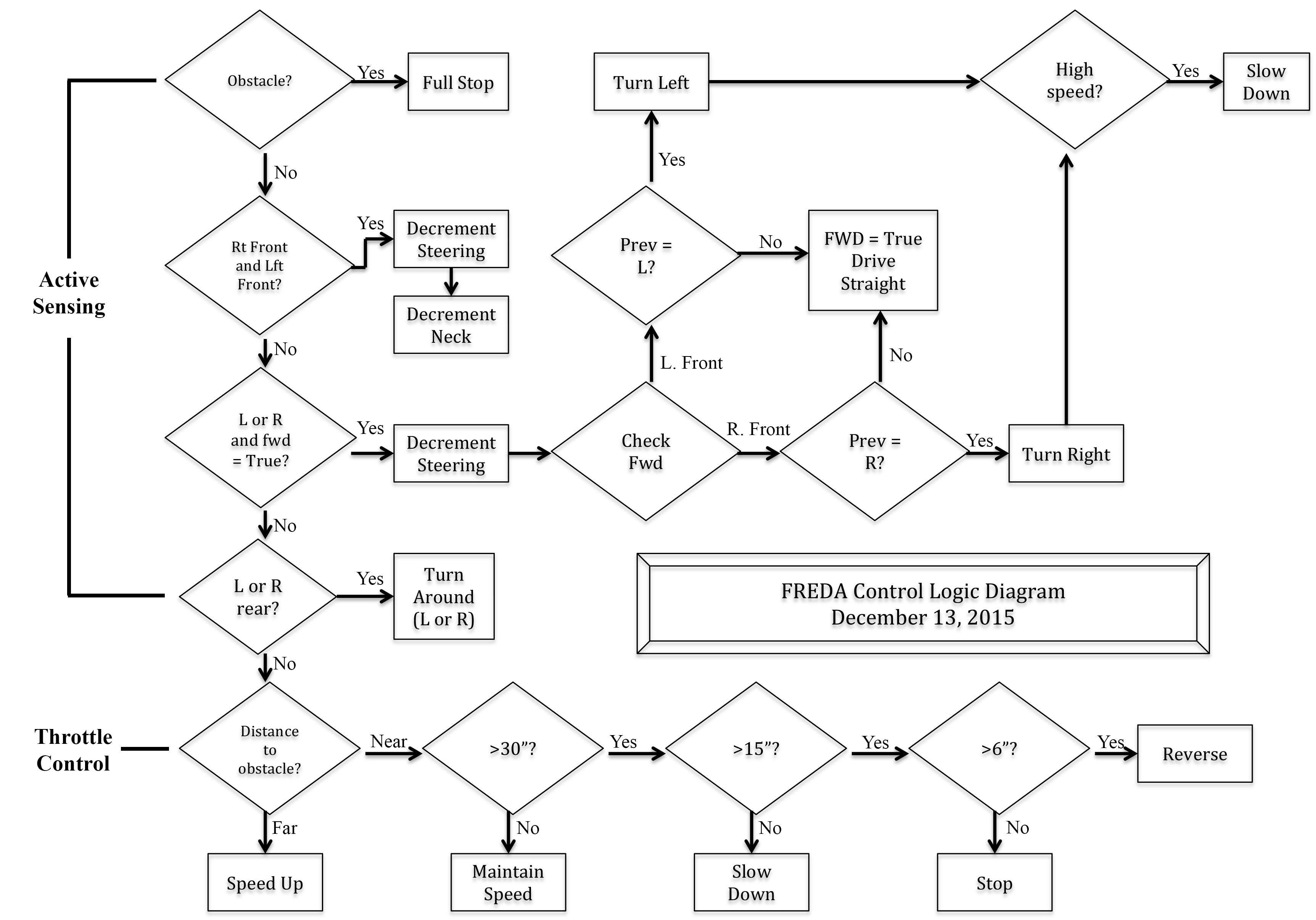
For my robotics final project, the goal was to get FREDA to follow me without crashing into anything. I decided to use a Pololu 2-part IR beacon, one of which I would keep on my person, and the other would be attached to FREDA’s head to enable active sensing and inform her path-planning algorithm. I would also use distance sensors about her nose to allow for obstacle avoidance. The major hurdle I have been encountering is discovering how best to code the Arduino controlling everything to allow for appropriately timed responses to sensor input. In other words, there’s a lot of trial and error, and she’s crashed a lot in the meantime.


Robot navigation is, in my opinion, one of the most important aspects of human-robot interaction, and is extremely relevant to the ever-expanding field of robotics. This particular project could lend itself specifically to fun toys, or even perhaps a robotic assistant. The much broader topic of navigating through an environment safely and effectively is already being widely explored by a number of researchers in the field, and lends itself to any environment in which a robot works in tandem with a human and safety is a concern.

Design

An Ongoing, Evolving Process

For the Robotics final project, I needed to incorporate sensing and actuation with some kind of path-planning algorithm. The end goal was for FREDA to follow me successfully without crashing into obstacles (including me).


When I began designing this project, I thought it would be fun to explore building a quadrupedal robot, but wanted to base it off an animal that had particularly deliberate movements that might lend itself nicely to robotic interpretation. With that in mind, I chose an iguana as my base model. I also thought this would be a fun experiment in discovering how animated a robot would have to be so that despite its obvious artificiality, people might identify with it as some kind of living creature. To that end, I decided a skeleton would be best, as it would obviate the creature’s inorganic nature while still echoing the basic building blocks of life.


At the start of the beacon-following portion of the project, the driving mechanism was one modified from an RC car, and so FREDA was able to drive and steer, but lacked neck movement. In order to enable active sensing, a servo was added to her neck, which would be used to check the direction of the beacon to inform steering. The original design did not account for the servo, so the “vertebrae” at the base of the neck was split open and used as servo housing, with the base of the servo attached to the skull and the rotating portion of the servo attached to the neck. Many zip ties and much thermoplastic was used to discover the best method for securing the servo.

Distance sensors had already been installed in the nose in anticipation of obstacle avoidance, so the only step left with these was to incorporate them into the algorithm. There are also accelerometers on three axes already installed in the skull, to be incorporated into her programming at a later date, perhaps to control the colors of her LEDs.


The end product so far is surprisingly durable, and has endured multiple crashes into walls without incident. In fact, the biggest source of error has been the wires plugged into the Arduino, which are not soldered, and so can become dislodged. To help this issue, the plugs have been taped to the board in place, but the solution is imperfect. If this were not an experiment but a final product, the wires would obviously be hard-connected to the processor.

The Arduino itself, while versatile, is limited in its computing power, and so is not as responsive as I would desire. I will be exploring other microprocessors in the future to find the one best suited to this application, in order to increase efficiency.

Implementation

Motors, servos, and sensors, oh my!


The chassis consists of a 3D printed skeleton wired with 31 RGB LEDs, which in the future will be used for communication and intrigue. FREDA has four-wheel drive controlled by a dual drive shaft modified from an Everest 1/10 scale Rock Crawler from Redcat Racing. The front and back steering are controlled in tandem with two 15kg servos (the rear has been manually reversed). They run off a single input. The wiring diagram below contains variable resistors that represent a joystick attached during motor and servo testing, and is not present in the final design.

The neck servo is another 15kg servo attached at the base of the skull and the end of the neck. The whole chassis is strung together with cables, wires, and springs, and in the future will be fully articulated. In its current incarnation, in order for the driving mechanism to work properly, the skeleton is held up over a solid frame which keeps the driveshaft in a specific configuration to maximize efficiency.

Wiring Diagram


For the beacon itself, I chose to house the infrared sensors within 3D printed flowers atop FREDA’s head for aesthetic reasons, while leaving the IR beacon chip viewable above the flower/ sensor array, so the user could see visual feedback of the beacon’s operation. There are four directional indicator LEDs atop the chip that light up when the companion beacon is detected in that direction, and it’s reaffirming and pleasing to see them light up.

The nose houses three IR distance sensors configured as binary inputs, and are currently programmed as kill-switches so that FREDA can park beside me and not move until I do. In the future, I would like to configure them as analog inputs that can inform steering to steer away from peripheral obstacles.

There is also a ping sensor housed at the base of her neck on her skull that informs her throttle. I am considering moving this to the other side of the neck, so that the throttle is informed by obstacles in the direction of travel, and not necessarily in the direction of her head (which may or may not be aligned to the direction of travel).


The code for this project, as I am a beginning programmer, is pretty basic, and I hope to increase both its efficiency and capabilities as I become a more proficient programmer.

The path planning algorithm is basically reactionary, as I want FREDA to be able to respond instantaneously to both obstacles and my own movement. Therefore, her throttle is informed by the distance sensor in her neck and the angle of her steering, and switched off by the obstacle detectors in her nose. Her steering is solely informed by the position of the beacon, though as mentioned I would like to add other inputs and/ or modify existing ones to allow for more precise navigation through an environment.

Click to download my code


The whole system incorporates the modified drive shaft and steering, the sensor array and neck servo, and my very basic code to control FREDA’s movements and allow her to follow me without crashing.

Results

She drives! ..sort of...

I am thrilled that this project is working to any degree at all, and am elated that I have been moderately successful in accomplishing my goals.

The active sensing unit works fantastically well. My original implementation oriented North on the beacon as face-forward, but through experimentation I discovered that aligning a junction between directions as face-forward allowed for the most accurate directional reading. FREDA’s head can move back and forth only a few minor degrees to check the boundary, and change her steering in accordance to her readings.

It was important, given the microprocessor being used and my own rudimentary coding skills, that the final implementation remained as simple as possible, not only to make sure I could actually code her properly, but also to allow for fast reaction times for changes in sensor conditions. I wanted her to be able to keep up with me at a walking pace, which seems to have been a worthy goal, and I am happy with the current results.


Conclusion

Ok, so this is an ongoing project, but we'll call it a conclusion anyway...

As this robot is a continuing tool for discovery, it comes as no surprise that much was discovered in the process of getting it to work, and much did not go as planned. I am still experimenting with the best algorithm, and am working on simplifying my code. The biggest issue at the moment still seems to be reaction time and her large turn radius, so that FREDA will drive past me for a few feet before stopping and reversing, or will overshoot if I am too close. She also has run into my legs at very low speeds. But, for the most part, she follows successfully, especially if I am farther ahead of her than just a few feet. It seems she has the most trouble at close ranges, which makes sense given her present turning radius. I hope to overcome this issue in the conversion from wheels to legs, which would give better dexterity and therefore allow her to explore her environment more precisely.

All in all, I am happy with my active sensing implementation, and believe it is the best learning experience of the past few months. I have a base understanding now, and can expand upon this implementation to improve accuracy and efficiency as my skills improve.

There is much left to explore with FREDA, and I am excited to discover how she will evolve. I plan to replace the wheels with legs, which is a task currently far beyond my capacity. Sketches and photos of the legs are included in "Additional Materials." I also plan to articulate her tail and spine, and even her jaw and eyes. All of this will be in an attempt to explore the boundary between artificial and organic, and discover how people's interactions with her change as she evolves.

About The creator


Elizabeth Sonder previously was the Costume Draper at Teatro Zinzanni before returning to school to study electrical engineering. She brings ten years of creative experience to the field, and is fascinated by robotics in particular. She is particularly interested in the fields of prosthetics and space exploration, and in the future would like to apply her talents to solve problems somewhere within these complex and fascinating arenas. She is currently studying Electrical Engineering and Computer Science at UC Berkeley, and will be graduating in December of 2017. She lives in North Berkeley with her husband Abara Isaac Sonder.

Additional Materials

Data sheets, sketches, code, etc


"